Measurement-Driven Sub-Network Selection for On-Premise Retrieval-Augmented Factory Agents
Supplementary answer-quality examples: per-question LLM-judge scores across compression pipeline stages, plus vision-tool and routing demonstrations.
Selection rule. Examples are not hand-picked: for each model, questions were sampled
deterministically at the 95, 75, 50, 25, 5th percentiles (badges) of that model's own per-question
judged-quality distribution (mean of faithfulness, answer relevancy, and context utilization), so the page includes
strong, typical, and weak answers. Scores are the per-question values from the paper's LLM-judge sessions
(Claude Opus 4.8, interleaved anonymized protocol). The three 3B systems were judged in one session on identical
questions and retrieved contexts, so their scores are directly comparable; the 1B session is separate and its
absolutes are not comparable to the 3B section. Retrieved contexts are truncated excerpts of the machine's operator
manual, quoted briefly for illustration.
1Same question across the 3B pipeline stages
Each card shows one question from the n=633 held-out set with the identical retrieval, answered by the
unpruned base model, the extracted rank-6 sub-network before adaptation, and the deployed rank-6 model after
retrieval-grounded distillation.
P95
What triggers the milling calculator to display the recommended power for the operation?
Retrieved context (truncated excerpt)
LEFT and RIGHT cursor arrow keys to choose from the available options. • wCalculated values appear highlighted in yellow when they are outside of the recommended range for the workpiece and tool material. Also, when all of the calculato…
Unpruned base 3B + RAGfaithfulness 0.90relevancy 1.00ctx. util. 1.00
Based on the provided data context, the milling calculator will display the recommended power for the operation when all of the calculator fields contain data (calculated or entered). This can happen in two scenarios:
1. When you have entered enough information into the calculator fields, it will automatically display the results in the relevant fields, which are marked with an asterisk (*). 2. When the calculator fields contain calculated values that fall outside of the recommended range for the workpiece and tool material, the calculated values will be highlighted in yellow to indicate that they are outside of the recommended range.
To view the recommended power for the operation, simply ensure that all the calculator fields have data entered, and the calculator will display the recommended power for the operation.
Extracted rank 6 (no Stage 2)faithfulness 0.70relevancy 0.50ctx. util. 0.60
The milling/turning calculator is a tool used to automatically calculate machining parameters based on given information. When you have entered enough information, the calculator displays results in the relevant fields marked with an asterisk (*).
The milling calculator triggers the display of the recommended power for the operation when all of the calculator fields contain data (calculated or entered). This is because the calculator automatically calculates and displays the relevant fields, marked with an asterisk (*), when you have entered enough information.
P75
How can I adjust the size of the zoom window?
Retrieved context (truncated excerpt)
6) Zoom Press F2 to display a rectangle (zoom window) that shows the area that the zoom operation will move to. Use PAGE DOWN to decrease the size of the zoom window (zoom in), and use PAGE UP to increase the size of the zoom window (zo…
Unpruned base 3B + RAGfaithfulness 0.95relevancy 0.95ctx. util. 0.95
To adjust the size of the zoom window, you can use the following methods:
- Press F2 to display a rectangle (zoom window) that shows the area that the zoom operation will move to. - Use the PAGE DOWN key to decrease the size of the zoom window (zoom in). - Use the PAGE UP key to increase the size of the zoom window (zoom out). - Use the cursor arrow keys to move the zoom window to the location you want to zoom. - Press ENTER to complete the zoom.
Additionally, you can also use the arrow keys to move the zoom window and press ENTER to finalize the zoom.
Extracted rank 6 (no Stage 2)faithfulness 0.90relevancy 0.85ctx. util. 0.85
To adjust the size of the zoom window, you can follow these steps:
1. Press F2 to display a rectangle (zoom window) that shows the area that the zoom operation will move to. 2. Use PAGE DOWN to decrease the size of the zoom window. 3. Enter to complete the zoom. 4. The control scales the tool path window to the zoom window. 5. Run the program again to display the tool path. 6. Press F2 and then HOME to expand the Tool Path window to cover the entire work area.
Note: If Setting 253 is ON, the tool diameter is shown as a thin line. If it is OFF, the tool diameter specified in the Tool Offsets Diameter Geometry table is used.
To adjust the size of the zoom window, you can use the following steps:
1. Press F2 to display a rectangle (zoom window) that shows the area that the zoom operation will move to. 2. Use the PAGE DOWN key to decrease the size of the zoom window (zoom in). 3. Use the PAGE UP key to increase the size of the zoom window (zoom out). 4. Use the cursor arrow keys to move the zoom window to the location you want to zoom. 5. Press ENTER to complete the zoom.
Additionally, you can also use the HOME key to expand the Tool Path window to cover the entire work area.
P50
What mode do you run programs in?
Retrieved context (truncated excerpt)
Highlight a program in the memory directory, then press SELECT PROGRAM to make the highlighted program active. The active program has an asterisk (*) in the far-right column in the file display. It is the program that runs when you press…
Unpruned base 3B + RAGfaithfulness 0.90relevancy 1.00ctx. util. 0.90
You're looking to know the mode in which you run programs. According to the provided data, the mode you run programs in is called "Operation:MEM" mode. This mode is also referred to as "Memory" mode. In this mode, you can run programs, and the active program is protected from deletion while it's running. Additionally, you can use the "CYCLE START" command to start the active program, and it will run when you press the "CYCLE START" button.
Extracted rank 6 (no Stage 2)faithfulness 0.85relevancy 0.50ctx. util. 0.70
Sure, I can help you understand the context and provide a helpful response.
The tool returned the following data context:
- Highlight a program in the memory directory, then press SELECT PROGRAM to make the highlighted program active. - The active program has an asterisk (*) in the far-right column in the file display. - It is the program that runs when you press CYCLE START in OPERATION:MEM mode. - The program is also protected from deletion while it is active.
So, to summarize, you can highlight a program in the memory directory and then press SELECT PROGRAM to make it active. The active program is protected from deletion and runs when you press CYCLE START in MEM mode.
To run programs in the Operation:MEM mode, you can select a program in the memory directory and press the "SELECT PROGRAM" button. This will make the highlighted program active, which is indicated by an asterisk (*) in the far-right column of the file display. The program is also protected from deletion while it is active.
P25
What types of activities should a machine operator not perform on their own?
Retrieved context (truncated excerpt)
may operate this equipment. You must always act in accordance with the Operator’s manual, safety decals, safety procedures, and instructions for safe machine operation. Untrained personnel present a hazard to themselves and the machine …
Unpruned base 3B + RAGfaithfulness 0.80relevancy 0.85ctx. util. 0.85
Based on the provided data, there are several activities that a machine operator should not perform on their own. These include:
- Operating the machine without proper training and understanding of the Operator's manual, safety decals, and safety procedures. - Using the machine without reading all warnings, cautions, and instructions first. - Installing or operating the machine without everyone involved being familiar with the operation and safety instructions. - Performing maintenance or repairs on the machine without factory-trained personnel. - Operating the machine without proper eye and ear protection. - Operating the machine without proper gloves to handle processed material and clean the machine. - Cleaning the machine without proper training and understanding of the machine's operation and safety instructions.
It's also important to note that some tasks, such as cutting tools, workholding, workpiece, and coolant, are beyond the control of the machine manufacturer and are the responsibility of the user to address.
Additionally, the data highlights the importance of following proper safety protocols, such as keeping the machine doors open
Extracted rank 6 (no Stage 2)faithfulness 0.75relevancy 0.60ctx. util. 0.60
To summarize, a machine operator should not perform any activities that put themselves or others at risk, such as operating the machine until they have read all warnings, cautions, and instructions provided with the machine. They should always use appropriate eye and ear protection, gloves, and follow safety procedures.
As a machine operator, there are certain activities that you should not perform on your own. These include:
1. Operating the machine without proper training and understanding of the safety procedures and instructions. 2. Using personal protective equipment (PPE) or gloves to protect yourself from potential hazards. 3. Handling sharp edges, heavy lifting considerations, and other potential hazards associated with the machine. 4. Cleaning the machine during normal use, which is a normal operator function. 5. Repairing the machine when it's not operating correctly, which requires service by factory-trained personnel.
It's essential to follow the guidelines and instructions provided with the machine, as well as the Operator's manual, safety decals, and safety procedures. The ultimate responsibility for safety rests with the machine owner and the individuals who work with the machine.
P5
What is the minimum software version required to find the last error in a program?
Retrieved context (truncated excerpt)
the first match. NOTE: Putting your search term within parentheses (), will search only within comment lines. Starting in software version 100.19.000.1100 the control can find the last error in a program. Press SHIFT + F4 to display the l…
Unpruned base 3B + RAGfaithfulness 0.95relevancy 1.00ctx. util. 0.90
To find the last error in a program, you need to have a software version of at least 100.19.000.1100. This version allows the control to detect and identify the last error in a program.
Additionally, you can use the "Locate the Last Program Error" feature to find the last error. This feature can be accessed by pressing SHIFT + F4, which will display the last line of G-code that generated the error.
Extracted rank 6 (no Stage 2)faithfulness 1.00relevancy 1.00ctx. util. 0.90
The minimum software version required to find the last error in a program is software version 100.19.000.1100.
To find the last error in a program, you can use the following steps:
1. Press SHIFT + F4 to display the last line of G-code that generated the error. 2. Locate the Last Program Error by searching for the error code in the program. 3. The error code is stored in the variable #6198. 4. To conditionally run program code for a specific control version, you can use the following code: - IF (#6198 EQ 1000000) GOTO5 - (Non-NGC code) - GOTO6 - N5 (NGC code) - N6 M30
This will allow you to test the control version and then conditionally run program code for that control version. If the value stored in #6198 is equal to 1000000, the program will end.
2Deployed 1B rank 5 (Arduino UNO Q tier)
Examples from the 1B grid's own judging session.
P95
What is the limited warranty coverage for CNC Machines and their Components?
Retrieved context (truncated excerpt)
conditions of this Certificate. Limited Warranty Coverage Each CNC Machine and its Components (collectively, “Haas Products”) are warranted by Manufacturer against defects in material and workmanship. This warranty is provided only to an…
Based on the provided data, the limited warranty coverage for CNC Machines and their Components is one (1) year. This warranty covers defects in material and workmanship, and it only applies to the end-user of the CNC Machine (a "Customer"). The warranty period commences on the date the CNC Machine is installed at the Customer's facility. Additionally, Haas provides an extension of the warranty period from an authorized Haas distributor, but this is only for new mills, turning centers, and rotary machines that are manufactured by Haas and sold by Haas or its authorized distributors.
P75
What is the Manufacturer's warranty for Haas products?
Retrieved context (truncated excerpt)
remedy under this warranty, with respect to any and all Haas products, shall be limited to repairing or replacing, at the discretion of the Manufacturer, the defective Haas product. Disclaimer of Warranty This warranty is Manufacturer’s s…
The manufacturer of Haas products, Haas Automation Inc., offers a limited warranty on certain products, including new mills, turning centers, and rotary machines, and their components. This warranty is limited to repairing or replacing the defective product at the discretion of the manufacturer.
The warranty does not cover damage or defect due to an external influence or matters beyond the reasonable control of Haas, such as theft, vandalism, fire, or weather conditions. Additionally, the warranty does not cover damage caused by an external influence, and it does not cover damage caused by an external influence or matters beyond the reasonable control of Haas.
It's also worth noting that the warranty is only valid for the first year of ownership, and it does not cover any other warranties, including "Warranty Extension" or "Other Warranties."
P50
What is the purpose of the Spindle Lubrication Sight Glass and the Axis Lubrication Oil Reservoir in a machine operator's manual?
Retrieved context (truncated excerpt)
10. Spindle Lubrication Sight Glass (2) 11. Axis Lubrication Oil Reservoir 12. Oil Pressure Gauge NOTE: More details are shown on the decals inside of the access door. 1 12 11 10 9 8 7 6 5 4 3 2 1 2 3 4 5 6 7…
Based on the provided data context, it appears that the Spindle Lubrication Sight Glass and the Axis Lubrication Oil Reservoir are used for regular maintenance and monitoring of the machine's components.
The Spindle Lubrication Sight Glass is used to visually inspect the spindle and axes, which are essential for maintaining the machine's precision and accuracy. This glass is typically located on the work enclosure or near the machine's operation area.
The Axis Lubrication Oil Reservoir, on the other hand, is used to store and maintain the lubrication for the axes. Regularly adding and cleaning lubricants is crucial to ensure the machine's smooth operation and prevent damage to the components.
In summary, the purpose of the Spindle Lubrication Sight Glass and the Axis Lubrication Oil Reservoir is to provide regular monitoring and maintenance of the machine's components, and to ensure the machine operates safely and efficiently.
P25
What are the names and functions of the three buttons on the machine operator's manual?
These buttons are part of the Secondary ATC Controls section, which likely controls the operation of the machine.
P5
Why is it important to secure the work platform with chains to the enclosure or bolts to the floor?
Retrieved context (truncated excerpt)
3. (Optional) 4. (Optional) 5. Rotary Index Button 1. Chain to Enclosure 2. Floor Anchor Bolt 3. Secure the work platform with chains to the enclosure or bolts to the floor. 1 2 5 4 1 2 3…
To secure the work platform with chains to the enclosure or bolts to the floor, it's essential to follow proper safety procedures. This is because the enclosure can be a hazardous area, especially when working with cutting tools and metalworking fluids.
When entering the enclosure, always ensure that you're not entering it when the machine is capable of automatic motion. This is crucial to prevent accidents and ensure a safe working environment.
Additionally, it's recommended to check your setup and tooling before starting machining operations. This includes verifying that the machine is properly secured and that you're using the correct tools and materials.
It's also worth noting that some models may have specific requirements for entering the enclosure, such as pressing the emergency stop button or powering off the machine. Always follow the manufacturer's instructions and take necessary precautions to ensure your safety.
In summary, securing the work platform with chains to the enclosure or bolts to the floor is a critical step in maintaining a safe and productive work environment. By following proper safety procedures and checking your setup and tooling, you can minimize the risk of accidents and ensure a successful machining operation.
3Vision tool and routing
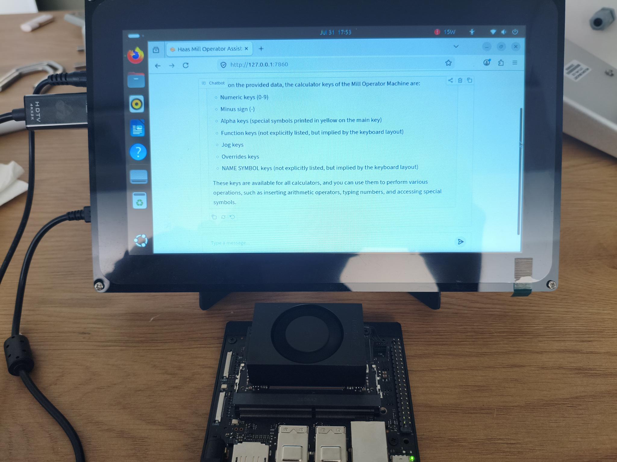
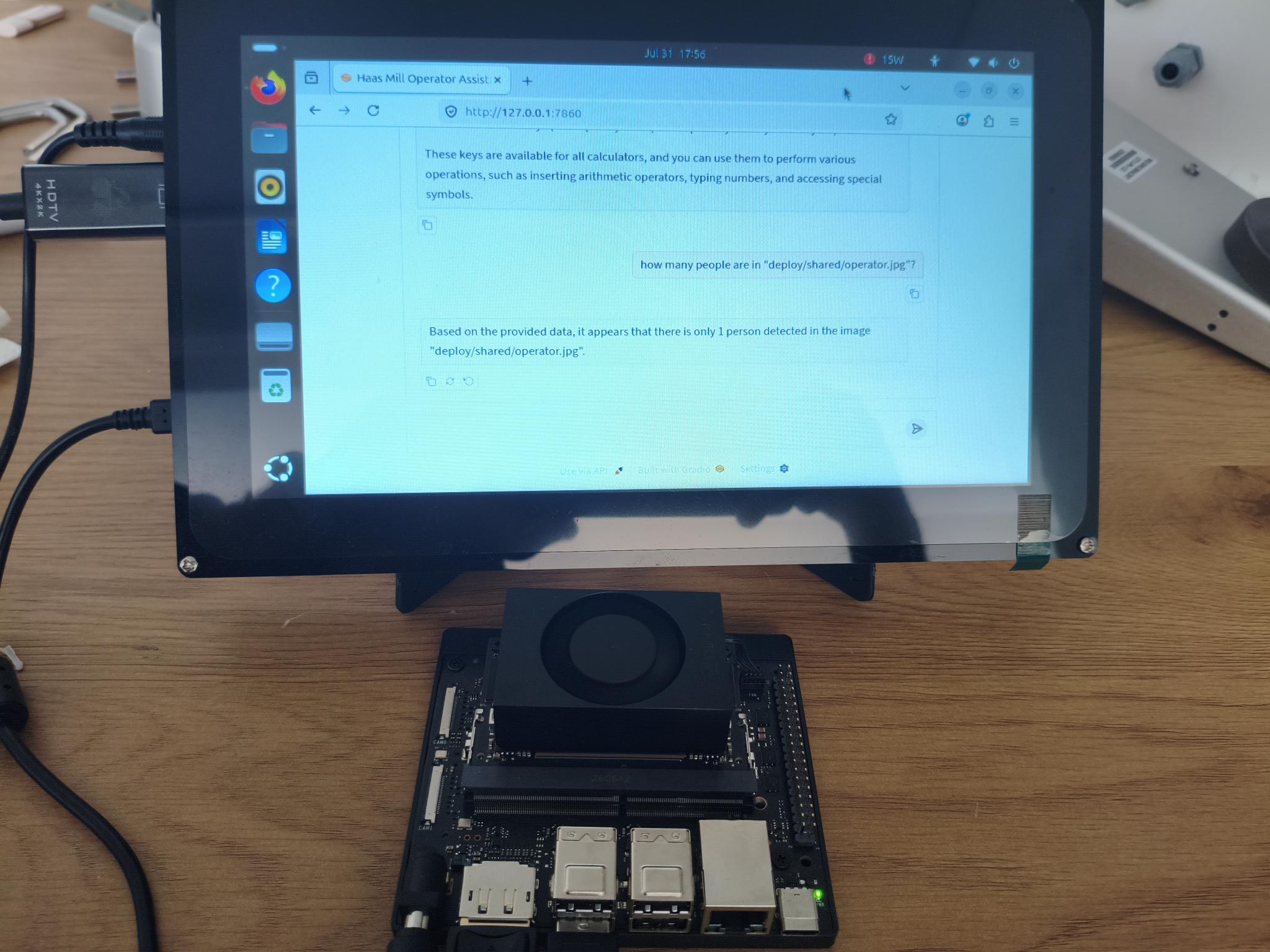
The assistant routes each query via a grammar-constrained JSON tool call either to manual retrieval or
to a person-detection vision tool, then answers from the tool output. Tool routing scored 40/40 on the held-out
routing set for every fine-tuned rank.
Manual question answered through the retrieval tool, on the Jetson tier.Person-count query answered through the vision tool.
Vision-tool input image (deploy/shared/operator.jpg): the frame the person detector analyzes for the query below.
Vision exchange: “how many people are in ‘deploy/shared/operator.jpg’?” →
“Based on the provided data, it appears that there is only 1 person detected in the image
‘deploy/shared/operator.jpg’.” (off-the-shelf person detector; reported as
functional, not accuracy-benchmarked)